S9013 NPS Transistor: Datasheet, Equivalent, How to Use

Catalog
S9013 Overview
S9013 Pinout
S9013 CAD Model
S9013 Applications
S9013 Alternatives
S9013 Typical Application Circuit
S9013 Functional Block Diagram
S9013 Package
Datasheet PDF
Specifications
How to use the S9013 NPN transistor
Product comparison
Advantages of the S9013 Transistor
Introduction
In the vast realm of electronic components, transistors play a crucial role in enabling the functionality of countless devices. Among these, the S9013 transistor stands out as a versatile and widely-used component. In this article, we will delve into the details of the S9013 transistor, exploring its specifications, applications, and the benefits it offers to electronic circuits.
Overview of the S9013 Transistor
The S9013 transistor is a popular general-purpose NPN bipolar junction transistor (BJT). It is designed to amplify and switch electronic signals, making it an essential component in various electronic circuits such as amplifiers, oscillators, and power control circuits. Manufactured in a small TO-92 package, the S9013 transistor is physically compact and easy to integrate into electronic designs.
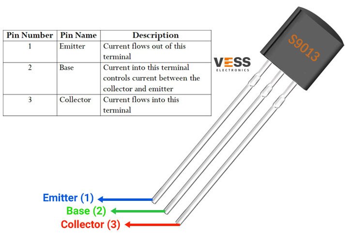
S9013 Pinout
S9013 CAD Model
Symbol

Footprint

3D-Model
S9013 Features
*25V collector-emitter breakdown
*500mA collector current
*Gain min. 40 and max. 300
*140MHz transition frequency
*TO-92 package with 650mW power dissipation
S9013 Applications
*High-frequency amplifiers
*Switching converters
*High-current drivers
Applications of the S9013 Transistor
The S9013 transistor finds wide-ranging applications due to its versatility and reliable performance. Some common applications include:
1. Amplification: The S9013 transistor is frequently employed as a small-signal amplifier in audio and radio frequency (RF) circuits. It can amplify weak signals to a level suitable for further processing or transmission.
2. Switching: With its ability to handle moderate currents and voltages, the S9013 transistor is often used as a switching element in electronic circuits. It can control the flow of current in a circuit, enabling the switching of devices or controlling power flow.
3. Oscillators: The S9013 transistor can be utilized in oscillators to generate continuous waveforms or create timing signals. This makes it useful in applications such as clock circuits and frequency generators.
4. Voltage Regulation: By configuring the S9013 transistor in various circuit arrangements, it can be employed in voltage regulation circuits. It helps stabilize and regulate voltages in power supplies and other electronic systems.
S9013 Alternatives
2N2222, 2N5551
S9013 Typical Application Circuit
S9013 Functional Block Diagram
S9013 Package
Dimension

Datasheet PDF
Please DOWNLOAD the datasheets and manufacturer documentation for the S9013 .
Specifications
Key Specifications
The S9013 transistor comes with several important specifications that define its performance characteristics. Here are the key specifications to consider:
1. Collector-Base Voltage (VCBO): This specification indicates the maximum voltage that can be applied between the collector and base terminals of the transistor.
2. Collector-Emitter Voltage (VCEO): It represents the maximum voltage that can be applied between the collector and emitter terminals.
3. Emitter-Base Voltage (VEBO): This specification denotes the maximum voltage allowed between the emitter and base terminals.
4. Collector Current (IC): The maximum current that can flow through the collector terminal is defined by this parameter.
5. DC Current Gain (hFE): Also known as the current transfer ratio, it indicates the amplification capability of the transistor.
How to use the S9013 NPN transistor
*Identify the pinout: The S9013 transistor has three pins: the emitter (E), the base (B), and the collector ©. Check the datasheet or the transistor package for the pinout diagram.
*Connect the emitter: Connect the emitter pin to the ground (GND) or the negative terminal of your circuit.
*Connect the base: Connect the base pin to the input signal source or the control circuitry. The base current controls the transistor’s behavior.
*Connect the collector: Connect the collector pin to the load or the output circuitry. The collector current flows through the transistor and powers the load.
*Add necessary resistors: Depending on your circuit requirements, you may need to add resistors. For example, you might connect a base resistor in series with the input signal to limit the current flowing into the base.
*Apply power: Connect the power supply to the appropriate terminals of your circuit.
*Test and troubleshoot: Once everything is connected, test your circuit and verify that it is functioning as expected. If there are any issues, check your connections, component values, and refer to the datasheet for guidance.
Product comparison
Advantages of the S9013 Transistor
The S9013 transistor offers several advantages that make it a preferred choice in various electronic designs:
1. Cost-Effective: The S9013 transistor is readily available at a low cost, making it an economical choice for both hobbyist and commercial projects.
2. Ease of Integration: Its compact TO-92 package allows for easy integration into electronic circuits, even in space-constrained designs.
3. Versatility: The S9013 transistor's ability to function as an amplifier and a switch, coupled with its moderate power handling capabilities, makes it suitable for a wide range of applications.
4. Wide Availability: The S9013 transistor is widely available from multiple manufacturers, ensuring a steady supply for designers and engineers.
Conclusion
In conclusion, the S9013 transistor is a versatile electronic component that finds applications in numerous electronic circuits. Its ability to amplify signals, switch currents, and regulate voltages makes it an invaluable tool for designers across various industries. Whether used in audio amplifiers, switching circuits, or oscillators, the S9013 transistor offers a cost-effective and reliable solution for electronic design needs.


Frequently Asked Questions
Related Articles

How Does Diode 1N4148 Work: Datasheet, Circuit
L293D & L293DD: Comparison, Datasheet
How Motor Driver L298N Works: Datasheet, Circuit
Transceiver NRF52840-DK: Equivalent
DS18B20+ Digital Thermometer: Unique 1-Wire Interface
MAX7219CWG Display Driver Ultimate Guide: Datasheet Released
Unleash Potential of PIC16F877A-I/P: Ultimate Embedded Solution
TOP245YN AC-DC Power Converter: Circuit Diagram
FT234XD-R Interface Bridge: Footprint, Datasheet, Alternatives
AD210AN Isolation Amplifier: Pinout, Applications, Datasheet
LD1117S33TR Voltage regulator: PDF, Pinout, Alternatives