How Does PC817 Optocoupler Work? Datasheet, Pinout, Equivalent
yunying Release time:2024-02-01 Page View:8358

- Introduction
- PC817 Detailed Description
- PC817 Pinout
- PC817 Features
- PC817 CAD-Model
- What is the alternative to PC817?
- What is the minimum voltage for optocoupler PC817?
- What is the use of PC817 optocoupler?
- What is the current limit for PC817?
- PC817 Application
- PC817 Package
- How Does PC817 Optocoupler Work?
- PC817 Vs PC123 Difference
- Conclusion
- Specifications
- Datasheets
- Product comparison
Introduction
PC817 is a popular optocoupler that serves as an essential component in various electronic circuits. It provides electrical isolation between input and output circuits, making it a reliable choice for applications that require signal transmission and noise reduction. In this article, we will delve into the working principles of PC817 optocoupler, its alternative options, minimum voltage requirements, common applications, and current limits.
PC817 Detailed Description
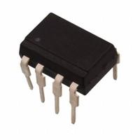
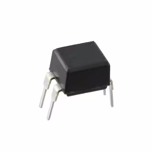
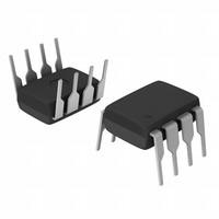
The PC817X Series is a type of optocoupler that consists of an infrared emitting diode (IRED) and a phototransistor. It is packaged in a 4-pin dual inline package (DIP) and is available in two options: one with wide-lead spacing and another with a surface-mount technology (SMT) gullwing lead-form.

This optocoupler provides electrical isolation between the input and output circuits, with an isolation voltage (rms) of 5.0kV. The collector-emitter voltage can withstand up to 80V(*), indicating its ability to handle higher voltage levels. The Current Transfer Ratio (CTR) of the optocoupler ranges from 50% to 600% when the input current is 5mA. This means that the output current of the phototransistor can be significantly higher than the input current, providing amplification or level shifting capabilities.
PC817 Pinout

PC817 Features
1. 4pin DIP package
2. Double transfer mold package (Ideal for Flow Soldering)
3. High collector-emitter voltage (VCEO:80V(*))
4. Current transfer ratio (CTR : MIN. 50% at IF=5 mA, VCE=5V)
5. Several CTR ranks available 6. High isolation voltage between input and output (Viso(rms) : 5.0 kV) (*) Up to Date code "P7" (July 2002) VCEO : 35V. From the production Date code "J5" (May 1997) to "P7" (July 2002), however the products were screened by BVCEO≥70V.
PC817 CAD-Model
Symbol

Footprint

3D-Model

What is the alternative to PC817?
While PC817 is widely used, there are alternative optocouplers available in the market. Some popular alternatives include PC814, PC816, and PC827. These alternatives possess similar functionalities and can be substituted for PC817 based on specific circuit requirements.
The replacement and equivalent of PC817 optocoupler are PC816, PC123, TLP621, TLP321, TLP421, PC17K1, H11A817, SFH615A, PS2501-1, PS2561-1, PS2571-1, LTV-816, LTV-817(-V), LTV123, LTV-610 K1010, K817P, SFH615A
What is the minimum voltage for optocoupler PC817?
The PC817 optocoupler typically requires a minimum input voltage, known as the forward voltage (Vf), for proper operation. The typical forward voltage for PC817 is around 1.2V, but it can vary slightly based on the specific model and manufacturer.
input voltage
What is the use of PC817 optocoupler?
PC817 optocoupler finds applications in a wide range of electronic circuits, including but not limited to:
- Signal isolation: It is commonly used to isolate high-voltage signals from low-voltage control circuits, preventing potential damage or interference.
- Voltage level shifting: PC817 facilitates converting signals between different voltage levels, ensuring compatibility between different parts of a circuit.
- Noise reduction: By providing electrical isolation, PC817 helps in reducing noise and interference caused by ground loops or high-frequency signals.
- Switching applications: It can be used as a reliable switch to control various electronic components or devices.
What is the current limit for PC817?
The PC817 optocoupler has a maximum current limit, known as the collector current (Ic). The specific value of the current limit depends on the model and manufacturer. Generally, the maximum collector current for PC817 ranges from 50mA to 80mA. It is crucial to ensure that the current through the optocoupler remains within its specified limits to prevent damage and ensure proper functionality.
PC817 Application
Here are a few additional examples of common applications for PC817 optocoupler:
1. Motor control: PC817 can be used to isolate and control the motor drive circuitry, allowing safe and precise control of motors in various applications such as robotics, industrial automation, and consumer electronics.
2. Power supply feedback: PC817 can provide feedback for voltage regulation and control in power supply circuits. It helps monitor and adjust the output voltage by isolating the feedback signal from the high-voltage power circuitry.
3. Audio signal transmission: PC817 is often utilized in audio circuits to transmit signals across different sections of an amplifier or audio system while maintaining isolation between the input and output stages. This helps to prevent noise interference and ground loop issues.
4. Switching power supplies: PC817 can be employed in switching power supply circuits to control the switching elements, providing isolation between the control circuit and the high-voltage power circuit. It helps regulate the power supply output accurately and efficiently.
5. Microcontroller interfacing: PC817 can be used to interface microcontrollers with high-voltage or noisy environments. It allows the microcontroller to receive signals from sensors or control external devices without being affected by the electrical noise or voltage differences.
6. Isolated communication interfaces: PC817 enables isolated communication between different systems or devices, such as UART, SPI, or I2C interfaces. It ensures reliable data transfer while protecting sensitive components from potential voltage spikes or ground potential differences.
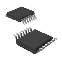
PC817 Package
4-DIP (0.300, 7.62mm)

How Does PC817 Optocoupler Work?
The PC817 optocoupler is a popular device used to isolate electrical circuits by using light to transfer signals between them. It consists of an infrared LED (light-emitting diode) and a phototransistor housed within a single package. Here's a brief overview of how it works:
1. Input side (LED): When a voltage is applied across the input terminals of the PC817, current flows through the internal LED. The LED emits infrared light when it is forward-biased.
2. Isolation: The input and output sides of the optocoupler are physically separated by a transparent insulation barrier. This isolation provides protection against voltage spikes, noise, and potential ground loops.
3. Output side (Phototransistor): The emitted infrared light from the LED falls on the phototransistor, causing it to conduct. The phototransistor's collector-emitter current (output current) is controlled by the intensity of the received light.
4. Signal transfer: By modulating the current through the LED on the input side, the output side phototransistor's current can be controlled, providing signal transfer between the input and output circuits without any direct electrical connection.
5. Amplification: The phototransistor output can then be used to control other components such as transistors, relays, or integrated circuits, amplifying the signal and allowing it to drive loads or perform other functions.
The PC817 optocoupler is commonly used for applications involving voltage level shifting, noise isolation, feedback control, signal isolation, and protection against voltage surges. Its operation is based on the principles of optoelectronics, where light is used to control electrical signals.
PC817 Vs PC123 Difference
The PC817 and PC123 are both optocoupler devices commonly used in electronic circuits to provide electrical isolation between input and output signals. While they have similar functionalities, there are a few key differences between the two:
1. Package Type: The PC817 and PC123 optocouplers are available in different package types. The PC817 typically comes in a DIP (Dual Inline Package) or SOP (Small Outline Package) form, while the PC123 is often found in a DIP package. The package type affects the physical size and pin configuration of the device.
2. Collector-Emitter Voltage: The collector-emitter voltage (VCEO) rating indicates the maximum voltage that can be applied across the collector and emitter terminals of the optocoupler. The PC817 typically has a higher VCEO rating compared to the PC123. The specific VCEO rating may vary depending on the manufacturer and model of the device.
3. Current Transfer Ratio (CTR): The current transfer ratio represents the ratio of output current to input current and is an important parameter for optocouplers. The PC817 and PC123 have different CTR ranges. The PC817 generally has a higher CTR compared to the PC123, meaning it can provide higher output current for a given input current.
4. Response Time: The response time of an optocoupler refers to the time it takes for the output signal to change in response to a change in the input signal. The PC817 typically has a faster response time compared to the PC123. A faster response time allows for quicker signal transmission and can be advantageous in applications where speed is important.
Conclusion
PC817 optocoupler is a versatile electronic component that enables electrical isolation and signal transmission in various circuits. Understanding its working principles, alternative options, minimum voltage requirements, common applications, and current limits can help engineers and hobbyists make informed decisions when incorporating it into their designs. Whether it's for signal isolation, voltage level shifting, noise reduction, or switching applications, PC817 optocoupler continues to be a reliable choice in the world of electronics.
Specifications
- Manufacturer :
- Sharp Microelectronics
- Product Category :
- Optoisolators - Transistor, Photovoltaic Output
- Current - DC Forward (If) (Max) :
- 10 mA
- Current - Output / Channel :
- 50mA
- Current Transfer Ratio (Max) :
- 600% @ 500µA
- Current Transfer Ratio (Min) :
- 100% @ 500µA
- Input Type :
- DC
- Mounting Type :
- Through Hole
- Number of Channels :
- 1
- Operating Temperature :
- -30°C ~ 100°C
- Output Type :
- Transistor
- Product Status :
- Obsolete
- Rise / Fall Time (Typ) :
- 4µs, 3µs
- Supplier Device Package :
- 4-DIP
- Turn On / Turn Off Time (Typ) :
- -
- Vce Saturation (Max) :
- 200mV
- Voltage - Forward (Vf) (Typ) :
- 1.2V
- Voltage - Isolation :
- 5000Vrms
- Voltage - Output (Max) :
- 80V
Datasheets
- Datasheets
- PC81710NSZ
Product comparison
-
ImagePart NumberManufacturerToleranceVoltage - RatedProduct StatusPackage / CaseProduct CategoryView Compare
-

-
-
Active
-
Optoisolators - Transistor, Photovoltaic Output
-
-
-
Active
-
Optoisolators - Transistor, Photovoltaic Output
-
-
-
Obsolete
-
Optoisolators - Transistor, Photovoltaic Output
-

-
-
Obsolete
-
Optoisolators - Transistor, Photovoltaic Output
- Share this post
-


Frequently Asked Questions
What is the current of PC817 transistor?
50mA Forward current. 6V Reverse voltage. 200mW Total power dissipation. Applications: Communications & Networking, Industrial.
What is the maximum voltage of PC817?
80 V. Maximum Collector Emitter Voltage(Output):80 V. Maximum Collector Current (Output) : 50 mA. Total power dissipation: 200mW. Operating temperature: −30 to +100 C.
Related Articles

2N5551 vs BC547 BJTs Comparison
LM3914 vs LM3915 vs LM3916 vs LM3917 How They Work?
Top 12 electronic component distributors 2024
TPS5450DDAR Datasheet, Pinout, Specification
C945 Transistor Datasheet:C1815 VS C945 Comparison
Lithium Battery Charger TP4056: Datasheet, Schematic, Price
TDA7265 Audio Amplifier:How To Connect And Test?
1n4007 vs 1n5399 Rectifier Diode: Pinout, Datasheet, Specifications
SN74HC595N vs SN74HC574N Shift Register Datasheet,Specs
H6 vs H7 vs H8 vs H9 Battery Difference and Choosing Guide

-
1,000+Daily Order Quantity
-
2,500,000+Alternative Parts
-
2,200+Worldwide Manufacturers
-
10,000 ㎡In-stock Warehouse