2N5551 vs BC547 BJTs Comparison
The 2N5551and BC547are both NPN bipolar junction transistors (BJTs) commonly used in various electronic circuits. While they share some similarities, there are also key differences between them, making them suitable for different applications. This article provides a comprehensive comparison of these two transistors, focusing on their specifications, features, and applications.
What is 2N5551?
The 2N5551 is a popular general-purpose NPN bipolar junction transistor (BJT). It is commonly used for amplification and switching applications in electronic circuits. The 2N5551 transistor has three terminals: the emitter (E), the base (B), and the collector (C).
Here are some key specifications of the 2N5551 transistor:
Maximum Collector-Base Voltage (Vcb): 160 volts
Maximum Collector-Emitter Voltage (Vce): 160 volts
Maximum Emitter-Base Voltage (Veb): 6 volts
Maximum Collector Current (Ic): 600 mA
Maximum Power Dissipation (Pd): 625 mW
DC Current Gain (hfe): Typically around 100 to 300
Transition Frequency (ft): 150 MHz
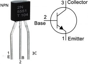
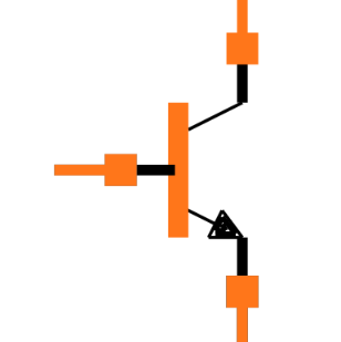
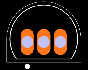
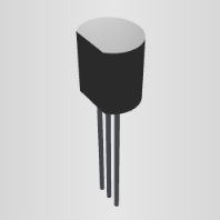
2N5551 Pinout 2N5551 Symbol 2N5551 Footprint 2N5551 3D-Model
What is BC547?
The BC547 is a widely used general-purpose NPN bipolar junction transistor (BJT). Similar to the 2N5551, it is commonly employed in various electronic circuits for amplification and switching purposes.
Here are some key specifications of the BC547 transistor:
- Maximum Collector-Base Voltage (Vcb): 50 volts
- Maximum Collector-Emitter Voltage (Vce): 45 volts
- Maximum Emitter-Base Voltage (Veb): 6 volts
- Maximum Collector Current (Ic): 100 mA
- Maximum Power Dissipation (Pd): 500 mW
- DC Current Gain (hfe): Typically around 110 to 800
- Transition Frequency (ft): 150 MHz
The BC547 transistor has three terminals: the emitter (E), the base (B), and the collector (C), similar to other NPN transistors. It is commonly available in a small TO-92 package.
BC547 Pinout BC547 Symbol BC547 Footprint BC547 3D-Model
Please refer to the BC547 datasheet, 2N5551 datasheet or specifications provided by the manufacturer for precise information on a specific BC547 transistor and 2N5551 transistor.
How does BC547 work?
+Vcc
|
R1
|
Input ---- B
|
|
---
---
|
E
|
GND
In this circuit, the BC547 transistor is used as a simple switch. Here's how it works:
The input signal is applied to the base (B) terminal of the transistor.
A resistor (R1) is connected between the base and the positive power supply (+Vcc) to bias the transistor.
The emitter (E) terminal is grounded.
The output is taken from the collector (C) terminal and is connected to the load.
When a sufficient input signal is applied to the base terminal, it causes a current to flow through the base-emitter junction, turning the transistor on. As a result, current can flow from the collector to the emitter, allowing the circuit to operate as a switch. If the input signal is below a certain threshold, the transistor remains off, and no current flows through the collector-emitter path.
This basic configuration allows the BC547 transistor to be used in various applications, such as controlling small motors, relays, or LEDs, as well as amplifying small signals.
How does 2N5551 work?
+Vcc
|
R1
|
Input ---- B
|
|
---
---
|
E
|
GND
In this circuit, the 2N5551 transistor is used as a common-emitter amplifier. Here's how it works:
The input signal is applied to the base (B) terminal of the transistor via a coupling capacitor.
A resistor (R1) is connected between the base and the positive power supply (+Vcc) to bias the transistor.
The emitter (E) terminal is grounded.
The output is taken from the collector (C) terminal and is connected to a load resistor or another stage of amplification.
When a small input signal is applied to the base terminal, the transistor amplifies it and produces a larger output signal at the collector terminal. The biasing resistor (R1) sets the operating point of the transistor, allowing it to operate in its linear amplification region.
2N5551 vs BC547 Specifications:
Feature | 2N5551 | NPN BJT |
Type | NPN BJT | NPN BJT |
Package | TO-92 | TO-92 |
Maximum Collector Current (Ic) | 600 mA | 100 mA |
Maximum Collector-Emitter Voltage (Vce) | 40 V | 45 V |
Maximum Collector-Base Voltage (Vcb) | 40 V | 50 V |
Maximum Power Dissipation (Pd) | 625 mW | 500 mW |
DC Current Gain (hFE) | 50 - 300 | 110 - 800 |
Transition Frequency (ft) | 300 MHz | 300 MHz |
Features:
High current handling capability: The 2N5551 can handle significantly higher collector currents compared to the BC547, making it suitable for applications requiring higher power.
Lower saturation voltage: The 2N5551 has a lower saturation voltage, which means it can achieve a higher current gain at lower base currents.
Higher gain-bandwidth product: Both transistors have a similar transition frequency, but the 2N5551 has a higher gain-bandwidth product, making it suitable for high-frequency applications.
Widely available and affordable: Both transistors are readily available and relatively inexpensive.
2N5551 vs BC547 Applications:
2N5551:
* Power amplifiers
* Switching circuits
* Motor drivers
* High-current applications
BC547:
* Low-power amplifiers
* Preamplifiers
* Logic circuits
* General-purpose applications
Conclusion:
The choice between the 2N5551 and BC547 depends on the specific application requirements. If high current handling capability is needed, the 2N5551 is the better choice. However, if lower power consumption or higher gain is desired, the BC547 is a more suitable option. Ultimately, understanding the specifications and features of each transistor is crucial for selecting the appropriate one for your project. You may send some RFQs to Vess Electronics to get your interested components parts.


Related Articles

How Does Diode 1N4148 Work: Datasheet, Circuit
L293D & L293DD: Comparison, Datasheet
How Motor Driver L298N Works: Datasheet, Circuit
Transceiver NRF52840-DK: Equivalent
DS18B20+ Digital Thermometer: Unique 1-Wire Interface
MAX7219CWG Display Driver Ultimate Guide: Datasheet Released
Unleash Potential of PIC16F877A-I/P: Ultimate Embedded Solution
TOP245YN AC-DC Power Converter: Circuit Diagram
FT234XD-R Interface Bridge: Footprint, Datasheet, Alternatives
AD210AN Isolation Amplifier: Pinout, Applications, Datasheet
LD1117S33TR Voltage regulator: PDF, Pinout, Alternatives